Getting Started With ESP 32 Development
ESP 32 is a series of low-cost, low-power system on chip micro controllers with integrated Wi-FI and Bluetooth. SoC or system on chip is an integrated circuit that integrates all or most of the component of a computer. Example the CPU, RAM, IO interface, GPU, etc. This form is becoming more and more popular thanks to growing smartphone and computing industry. Apple M1 chip is a good example on the direction in which SoC’s are going.
The ESP 32 is really low cost it cost like 350 in India, and less than 10$ in the US. Now when you buy this you don’t buy the chip alone, but a chip on a development board. There are several articles (https://makeradvisor.com/esp32-development-boards-review-comparison/) on that. The board that I bought from amazon was this https://www.amazon.com/dp/B0718T232Z?psc=1&ref=ppx_yo2ov_dt_b_product_details, i also bought one with OLED display as well https://www.amazon.com/dp/B07DKD79Y9?psc=1&ref=ppx_yo2ov_dt_b_product_details.
In this article I will be talking about how to get started. We will basically will be setting up Aurdino IDE in linux, followed by flashing few sample programs like:
Note: Arduino is another chip like esp32 (costlier but similar). ESP32 is can be made working on the same IDE. ESP32 can also be programmed using circuit python (which uses micro python), mruby, etc. But since there are a lot of popular code examples available for Arduino IDE esp32, I personally recommend getting started and working with Arduino.
The language used in Arduino is C++, and the C++ program is written to esp32 board using python (esptool.py).
To setup Arduino:
1. Download the linux installation files from https://www.arduino.cc/en/software
2. Extract the contents of the file downloaded ( a .tar.xz) to the home folder
3. Open terminal
4. cd ~/<folder_name>`` 5. sh install.sh`
This would install Arduino IDE in your computer, after which connect the esp32 device to your computer USB port.
Now do ls -l /dev/ttyUSB*. You will see the USB port number to which you have connected the board.
The output would look like this:
|
|
You need to add your logged in user to the group dialout for the IDE to be able to access the board. So run the following command.
|
|
You will have to log out and log back in for the settings to take hold, you could also quickly restart your computer if you wish.
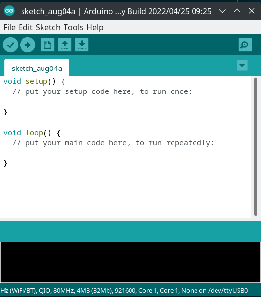
Once this is done, you can open up your Arduino IDE
Next step is to add the board details to the Arduino IDE.
To do that, go to:
- File > Preference
- In the section additional boards manager URL text box, paste the following urls:
``
1https://raw.githubusercontent.com/espressif/arduino-esp32/gh-pages/package_esp32_index.json, http://arduino.esp8266.com/stable/package_esp8266com_index.json
Now this will load a log of ESP32 and ESP8266 board details and chances are this would have your board as well.
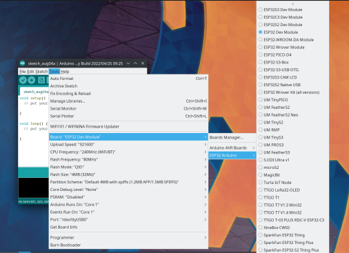
I selected the ESP32 Dev Module in the list.
Now, since we have our board selected, we can run some examples. When we added the preference URL, along with getting the board details it also got some examples. A good code to get started with is the wifi scan. To load the program go to file > examples > Under Heading Examples for ESP32 Dev Modules > WiFi > Wifi Scan
A window will open up with the code example.
Click the right arrow and it will start writing the code to the board.
Once you get started you might/will (depending on the board) see this following error.
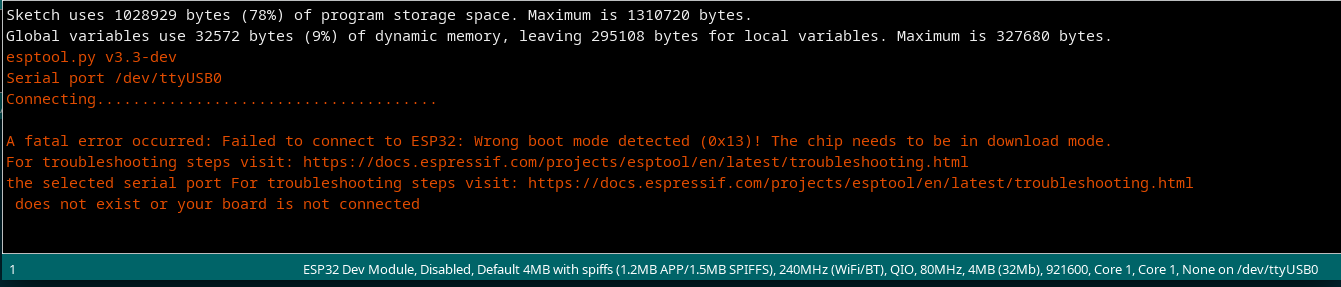
Failed to connected to ESP32: Wrong boot mode detected (0x13)! The chip needs to be in download mode.
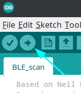
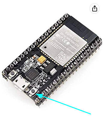
What this means is that you need to enable the download mode on the chip, and to do that you need to click and hold the boot button on the board while the program tries to upload the program. The below image is where the button is on my board, it would most probably be the same for you as well.
Now when you click the right button, you will see that it is overwriting what ever existing program it might be having.
To see the output of your work, click the magnifying glass on the top right corner of your Arduino board.
That Serial monitor, click the other button on your board and your program will now be running and it will slowly start to display all the wifi networks it can see.
There are other examples available as well feel free to play around with your board, and build something amazing.
PS: my board says ESP32-WROOM, its not that much different from ESP32 it just has more flash memory.
Code to control the onboard LED Light:
|
|
Code to control the onboard LED light using a HTTP server
|
|
Happy Codding